
Loudspeaker processing 9 min read
Loudspeaker Processing: Crossovers, Voicing, Polarity and Alignment
Understand crossover behavior, manufacturer voicing, polarity and time alignment, and apply them to complete loudspeaker systems.
- Explain what a crossover does.
- Distinguish speaker voicing from room EQ.
- Understand common crossover slopes and filter families.
- Explain the difference between polarity and phase alignment.
- Organize loudspeaker processing so that system designs remain understandable and serviceable.
Why an AV engineer should care
A loudspeaker’s “input” may look like one simple wire, but what happens before that wire can determine whether the system sounds clear, harsh, thin, muddy, or expensive.
Loudspeaker processing serves several different purposes:
- Dividing audio among drivers or loudspeaker types
- Protecting drivers from frequencies they cannot reproduce safely
- Correcting the loudspeaker’s native response
- Aligning drivers and loudspeakers in time
- Establishing safe output limits
These functions often get bundled into a manufacturer preset. Calling that preset “speaker EQ” undersells it. It may contain crossovers, polarity changes, very short delays, EQ, gain offsets, and limiters. Q-SYS’s custom-voicing controls, for example, include crossover filters, gain, polarity, and delay—not merely EQ. (help.qsys.com)
The basic problem: one driver cannot do everything well
A large woofer moves enough air to reproduce low frequencies, but its mass and geometry make it less suitable for high frequencies. A small compression driver or tweeter can reproduce high frequencies efficiently, but feeding it powerful low-frequency content may damage it.
A crossover divides the signal into frequency bands:
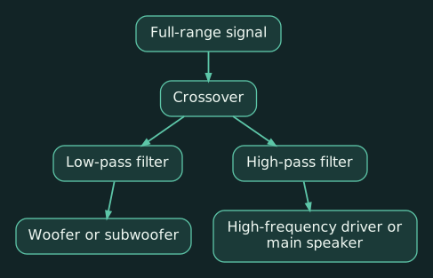
A low-pass filter allows frequencies below its cutoff region to pass and progressively reduces higher frequencies.
A high-pass filter does the opposite.
A two-way loudspeaker therefore typically sends lower frequencies to the woofer and higher frequencies to the high-frequency driver. A three-way system adds a midrange band. Commercial DSP crossover blocks may provide two through six bands, depending on the platform. (help.qsys.com)
The crossover frequency is not a brick wall
Suppose a crossover is set to 2 kHz. The woofer does not reproduce everything perfectly up to 1,999 Hz and then suddenly stop. Both drivers operate through a transition region. Their outputs overlap and must combine acoustically.
That overlap is where things get interesting.
The result depends on:
- Filter slope
- Filter type
- The drivers’ natural frequency responses
- Physical distance between the drivers
- Horn and enclosure behavior
- Polarity
- Electrical and acoustic delay
- The listener’s position
Therefore, an electronic crossover setting is only part of the acoustic crossover. Two filters both labeled “2 kHz” do not guarantee that the sound in the room will combine correctly.
Slopes: how quickly the filter turns down
Crossover slopes are usually expressed in decibels per octave.
An octave represents a doubling or halving of frequency. If a low-pass filter is set at 1 kHz, the next octave upward is 2 kHz.
Common slopes include:
| Filter order | Nominal slope |
|---|---|
| First order | 6 dB/octave |
| Second order | 12 dB/octave |
| Third order | 18 dB/octave |
| Fourth order | 24 dB/octave |
| Eighth order | 48 dB/octave |
A steeper filter reduces unwanted frequencies more quickly, but “steeper” does not automatically mean “better.” The slope changes the phase relationship and the way adjacent bands combine.
A 24 dB/octave slope is common in professional loudspeaker processing because it provides useful separation without requiring an absurdly sharp filter. It is still a design choice, not a universal default.
Butterworth, Linkwitz-Riley, and Bessel
These names describe different mathematical filter alignments.
| Filter family | General behavior | AV use |
|---|---|---|
| Butterworth | Flat response within an individual filter’s passband | General filtering and some crossover designs |
| Linkwitz-Riley | Designed so adjoining bands can sum predictably when properly aligned | Very common for loudspeaker crossovers |
| Bessel | Prioritizes smooth phase and time-domain behavior | Useful where transient behavior matters |
| Chebyshev | Sharper transition at the expense of passband ripple | Less common for ordinary installed-speaker crossover work |
A fourth-order Linkwitz-Riley crossover, commonly shown as LR24, places both bands 6 dB down at the crossover frequency. When the actual acoustic outputs are time-aligned and have the intended polarity, the bands can sum to a flat magnitude response.
That last sentence contains the trap: the filter mathematics assume the drivers cooperate. Real drivers bring their own response, delay, and physical offset.
Use the loudspeaker manufacturer’s filter type, slope, frequency, polarity, and delay values when supplied. Do not translate “2 kHz crossover” into a homemade generic filter and assume it is equivalent.
Speaker voicing versus room EQ
These should be treated as separate jobs.
Manufacturer voicing
Manufacturer voicing makes the loudspeaker behave as its designer intended. It may include:
- Driver crossovers
- Driver-specific EQ
- Horn correction
- Gain matching between drivers
- Polarity changes
- Fractional-millisecond driver alignment
- Excursion protection
- Thermal or voltage limiting
Room EQ
Room EQ addresses how the completed loudspeaker system interacts with the installed environment:
- Boundary reinforcement
- Broad tonal imbalance
- Speaker-to-speaker consistency
- Some effects of mounting position
- Appropriate response shaping for the room’s use
Room EQ cannot repair everything. Deep comb-filter notches caused by destructive interference should not be filled with heroic boosts. That wastes amplifier power while the two sources continue canceling each other.
Biamp’s loudspeaker-equalization guidance similarly emphasizes that the final response depends on arrival time, phase, level, and interaction among loudspeakers and the room. (support.biamp.com)
A useful processing order is:
- Program source and room mixing
- System or room EQ
- Manufacturer loudspeaker voicing
- Crossover and driver alignment, if not already included
- Manufacturer-approved limiting
- Amplifier and loudspeaker
The exact blocks can live in different devices. What matters is documenting which device owns each function.
High-pass filters as protection
Even a nominally full-range ceiling speaker may benefit from a high-pass filter below its useful range. Removing unusable low-frequency energy can reduce:
- Excess cone excursion
- Distortion
- Transformer stress in 70-volt systems
- Amplifier power consumption
- Unhelpful ceiling and wall vibration
The correct cutoff depends on the loudspeaker, transformer tap, enclosure, required level, and manufacturer’s data. “Put everything at 80 Hz” is not an engineering standard.
Similarly, a subwoofer crossover is not automatically 80 Hz. That may be a reasonable starting point, but coverage, available output, speaker response, and localization all matter.
Polarity is not the same as phase
A polarity inversion swaps positive and negative:
- Positive pressure becomes negative.
- Negative pressure becomes positive.
- The entire waveform is inverted at every frequency.
A time delay shifts the waveform later. Its phase effect changes with frequency.
That means a polarity button cannot globally repair a time-alignment problem. It may improve the summation around one crossover region while making another region worse.
At approximately 20°C:
- 1 millisecond ≈ 0.343 metres
- 1 millisecond ≈ 1.13 feet
Very short delays can align drivers within a cabinet. Longer delays can align a nearby fill loudspeaker with a main loudspeaker whose sound travels farther to the listener. DSP platforms may offer fractional delay specifically for this type of alignment. (help.qsys.com)
Commercial-AV example 1: ceiling loudspeaker system
Consider a Tesira DSP feeding a Crown amplifier and 70-volt ceiling loudspeakers.
A clean design might place:
- Mixing and room EQ in Tesira
- Speaker-specific processing in the Crown amplifier, if a verified preset exists
- The protective high-pass filter in exactly one documented location
- Output limiting in the amplifier
- Tap settings and total connected load in the loudspeaker schedule
Avoid putting one high-pass filter in Tesira, another in the amplifier, and an undocumented preset in between. The system may work, but the next engineer will need an archaeological permit.
The closeout package should identify:
- Preset name and version
- Amplifier channel
- Speaker model and transformer tap
- High-pass frequency, slope, and type
- Limiter settings
- Room-EQ location
- Any polarity or delay changes
Commercial-AV example 2: Multipurpose room with tops and subwoofer
A divisible meeting or presentation room has two full-range loudspeakers and a subwoofer.
Start with the manufacturer’s recommended crossover. If none is available, an LR24 alignment may be a reasonable design starting point—not the finished result.
Commissioning should include:
- Listen to or measure the sub alone.
- Listen to or measure the tops alone.
- Combine them.
- Inspect the response around the crossover.
- Test the intended polarity options.
- Adjust delay based on acoustic arrival, not just rack-to-speaker cable length.
- Confirm performance in combined and divided modes.
If a large notch appears near the crossover, check timing and polarity before adding EQ. A 10 dB boost aimed into cancellation is mostly a small space heater with a waveform attached.
Compact glossary
- Crossover: Filters that divide audio into frequency bands.
- HPF: High-pass filter; reduces frequencies below its cutoff.
- LPF: Low-pass filter; reduces frequencies above its cutoff.
- LR24: Fourth-order Linkwitz-Riley crossover with a nominal 24 dB/octave slope.
- Voicing: Manufacturer processing intended to produce the loudspeaker’s target behavior.
- Polarity: The positive/negative orientation of the signal.
- Phase: Frequency-dependent timing relationship between signals.
- Acoustic crossover: The measured combination of the filters, drivers, enclosure, placement, and timing.
- Fractional delay: Delay resolution smaller than one audio sample, used for precise alignment.
Practical exercise
In an offline DSP file, create a two-way crossover at 1 kHz:
- Low band: LR24 low-pass
- High band: LR24 high-pass
Observe the individual response curves and their overlap. Then:
- Change both filters to Butterworth.
- Invert the high band’s polarity.
- Add 0.5 ms of delay to the high band.
- Observe how the predicted combined response changes.
The graph demonstrates the electrical relationship. It still does not include the real drivers, enclosure, mounting, or room. That difference is why measurement matters.
Review questions
- Why is a manufacturer loudspeaker preset more than an EQ curve?
- What is the difference between speaker voicing and room EQ?
- Why can’t a polarity inversion fully correct a delay problem?
Answers
-
It may contain crossovers, driver EQ, gain offsets, polarity, delay, protection filters, and limiters.
-
Speaker voicing corrects and protects the loudspeaker itself. Room EQ addresses the installed system’s interaction with the room.
-
Polarity inversion flips the waveform at every frequency. Delay creates a frequency-dependent phase shift, so the two operations are not equivalent.