
IIR and FIR filters 10 min read
IIR and FIR Filters: Frequency, Phase, Taps and Latency
Compare recursive and finite-impulse-response filters, calculate FIR delay and choose processing with phase and latency in mind.
- Explain impulse response and filter coefficients.
- Distinguish IIR from FIR processing.
- Understand taps, filter length and FIR latency.
- Compare minimum-phase and linear-phase behavior.
- Decide when FIR processing is appropriate in commercial AV.
Why an AV engineer should care
Most familiar DSP filters—parametric EQ, high-pass filters and conventional crossovers—are IIR filters. They are efficient, responsive and require little processing latency.
FIR filters offer another level of control. Properly designed, they can correct magnitude and phase independently, create extremely precise crossovers, align drivers and implement manufacturer loudspeaker presets that would be difficult to reproduce with ordinary EQ.
That does not make FIR automatically superior. Long FIR filters consume DSP resources and add latency. A manufacturer-designed FIR preset can be excellent; a random collection of exported coefficients is merely a very complicated way to make the system worse.
1. What is an impulse response?
Imagine sending a DSP one extremely short pulse containing energy across the frequency spectrum. The processor’s output shows how it reacts over time.
That output is the filter’s impulse response.
A simple filter may respond briefly and settle immediately. A resonant filter may continue producing progressively smaller values after the original impulse has ended.
The impulse response contains the same fundamental information as the filter’s frequency and phase responses, presented in the time domain.
This leads to the names:
- IIR: Infinite Impulse Response
- FIR: Finite Impulse Response
“Infinite” is mathematical language. It does not mean an IIR filter continues ringing loudly until someone reboots the Core. Its response theoretically decays forever because previous outputs feed back into the calculation.
2. How an IIR filter works
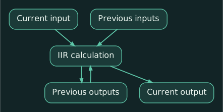
An IIR filter calculates each output from:
- Current input samples
- Previous input samples
- Previous output samples
That last item creates feedback inside the filter—not acoustic feedback through a microphone and loudspeaker, but mathematical recursion.
IIR filters are commonly organized as biquads, or second-order filter sections. Parametric EQ bands, Butterworth filters and Linkwitz-Riley crossovers can be built from cascaded biquads.
IIR advantages
- Low computational cost
- Few coefficients
- Very low processing latency
- Excellent for ordinary EQ and crossover work
- Familiar frequency, gain and Q controls
- Similar behavior to traditional analog filters
IIR limitations
IIR filters normally change phase along with magnitude. A high-pass filter affects level below its cutoff, but it also rotates phase through the transition region.
That is not automatically a defect. Analog filters do the same thing, and many excellent loudspeakers use IIR processing. It becomes a limitation when the design requires independent, precise control of magnitude and phase.
Q-SYS provides custom IIR filters specifically for loading calculated magnitude-and-phase filter sections, in addition to its conventional filter components. (help.qsys.com)
3. How an FIR filter works
An FIR filter calculates its output from the current input sample and a defined number of previous input samples. It does not recursively feed previous outputs back into itself.
Each delayed sample is multiplied by a coefficient. The weighted samples are then added together.
Each coefficient is commonly called a tap.
A simplified four-tap filter is:
y[n]=b₀x[n]+b₁x[n-1]+b₂x[n-2]+b₃x[n-3]
Where:
xis the inputyis the outputnis the current sampleb₀throughb₃are coefficients
A real loudspeaker-correction filter may use hundreds or thousands of taps. Q-SYS’s custom FIR component, for example, supports loading coefficients that define the desired magnitude and phase response. (help.qsys.com, help.qsys.com)
FIR advantages
- Precise control of magnitude response
- Precise control of phase response
- Linear-phase filters are possible
- Very steep filters are possible
- Useful for driver correction and crossover design
- Useful for beam shaping and array optimization
- Guaranteed mathematical stability when conventionally implemented
FIR limitations
- Greater DSP-resource consumption
- More difficult to design correctly
- Longer filters add latency
- Low-frequency correction requires many taps
- Linear-phase filters may produce pre-ringing
- Correction remains valid only within the physical limits of the loudspeaker and measurement conditions
4. Taps, length and frequency resolution
At 48 kHz, one sample lasts:
1 / 48,000 s ≈ 20.83 μs
A 2,048-tap FIR filter spans:
2,048 / 48,000 s ≈ 0.04267 s = 42.67 ms
For a symmetrical linear-phase FIR filter, the principal group delay is approximately half that length:
(2,048 − 1) / (2 × 48,000) s ≈ 0.0213 s = 21.3 ms
Biamp similarly documents that one of its 2,048-tap loudspeaker FIR filters adds approximately 21 ms of latency. (support.biamp.com)
Approximate linear-phase delays at 48 kHz are:
| Tap count | Filter span | Approximate group delay |
|---|---|---|
| 256 | 5.3 ms | 2.7 ms |
| 512 | 10.7 ms | 5.3 ms |
| 1,024 | 21.3 ms | 10.7 ms |
| 2,048 | 42.7 ms | 21.3 ms |
Actual device latency can also include buffering and other processing.
More taps provide greater control, especially at lower frequencies. A useful rough measure is:
Frequency-bin spacing ≈ (sample rate) / (tap count)
At 48 kHz:
- 256 taps: approximately 188 Hz
- 2,048 taps: approximately 23 Hz
That helps explain why detailed low-frequency correction demands long filters. Biamp recommends modest FIR tap counts combined with IIR filters when a system needs useful resolution without excessive latency. (support.biamp.com, support.biamp.com)
5. Minimum phase and linear phase
Minimum-phase filter
A minimum-phase filter places as much of its response as possible near the beginning of the impulse response. It provides the least latency available for that magnitude response.
Its phase response changes with frequency, much like conventional IIR filtering.
Linear-phase filter
A linear-phase filter delays all frequencies by the same amount. The waveform’s frequency components maintain their relative timing through the filter.
Q-SYS describes its FIR options this way:
- Linear phase: Same delay for all frequencies
- Minimum phase: Minimal delay that varies with frequency (help.qsys.com, help.qsys.com)
Linear phase can be valuable for:
- Loudspeaker-driver alignment
- Phase-consistent crossovers
- Array processing
- Correcting a loudspeaker’s measured phase response
- Preserving waveform relationships between frequency bands
It is not always necessary. Normal speech reinforcement rarely needs every frequency to have perfectly flat phase if achieving that adds objectionable latency.
6. Pre-ringing
A symmetrical linear-phase FIR filter may place part of its impulse response before the central peak. Because the entire signal is delayed, the filter is not actually responding before receiving the input. The output can, however, contain oscillation preceding the main reconstructed transient.
This is called pre-ringing.
It is most likely to become audible when:
- The filter is extremely steep
- Heavy correction occurs at low frequencies
- The source contains sharp transients
- The FIR is unnecessarily long or aggressive
Post-ringing occurs after the transient and is common to many resonant filtering processes. Human hearing can be more sensitive to pre-ringing because natural acoustic events generally do not announce themselves before the main event.
Good FIR design balances magnitude, phase, transition width, tap count and latency. “Linear phase everywhere” is a specification, not automatically a sonic improvement.
7. What FIR cannot fix
An FIR filter cannot:
- Restore output beyond a driver’s physical capability
- Repair a damaged loudspeaker
- Remove room reverberation
- Correct every seat simultaneously
- Fill deep spatial cancellations safely
- Fix poor loudspeaker aiming
- Make two badly positioned sources combine everywhere
- Eliminate distortion from an overloaded amplifier or driver
An inverse filter may flatten one measurement position while making other positions worse. Off-axis behavior and room interaction remain physical.
Use FIR primarily to correct predictable loudspeaker and array behavior. Use speaker placement, acoustic treatment, level, delay and coverage design to address the room.
8. Practical example: manufacturer FIR loudspeaker preset
Consider a Q-SYS Core feeding CX-Q amplifiers and Q-SYS loudspeakers, or a Biamp Tesira system feeding Voltera amplifiers and Biamp loudspeakers.
The manufacturer preset may combine:
- FIR driver correction
- IIR room-adjustment bands
- Crossover filters
- Driver delay
- Polarity
- Gain offsets
- Limiting
Biamp’s current Voltera workflow supports up to 2,048 FIR taps at 48 kHz and recommends placing speaker correction on outputs while retaining separate filters for on-site adjustments. (support.biamp.com)
The system designer should document:
- Loudspeaker model
- Manufacturer preset name and revision
- Required amplifier model
- FIR tap count or stated latency
- Which device contains the preset
- Separate site-specific room EQ
- Any paths requiring delay compensation
Do not manually recreate a manufacturer FIR preset from a screenshot of its magnitude curve. The unseen phase response is part of the design.
9. Practical example: conferencing and voice lift
A 21 ms FIR delay may be harmless for prerecorded program audio. It may be noticeable in local voice lift, where the talker hears both:
- Their natural voice directly
- Their amplified voice from the loudspeakers
Long processing delay can make speech reinforcement feel detached or echo-like. It also affects AEC-reference timing and synchronization with other audio paths.
For a conference room:
- Manufacturer loudspeaker FIR processing may still be appropriate.
- All loudspeaker zones intended to combine should have compatible latency.
- The AEC reference and microphone path must remain within the platform’s supported design.
- Avoid inserting long experimental FIR filters into live microphone paths.
- Match bypass or emergency paths so switching does not create a sudden timing change.
Latency belongs in the design calculation, not in the commissioning surprise pile.
Practical exercise
At 48 kHz, calculate the approximate delay of a symmetrical 1,024-tap linear-phase FIR:
(1,024 − 1) / (2 × 48,000) s ≈ 0.01066 s = 10.66 ms
Now imagine one loudspeaker zone uses that FIR while an adjacent zone uses only IIR processing.
- What happens when both reproduce the same signal?
- How much delay should be added to the faster zone as a starting point?
- What should be measured before finalizing it?
Troubleshooting answer: The zones arrive roughly 10.7 ms apart before acoustic-path differences, creating comb filtering where they overlap. Delay the faster path initially by the FIR’s measured processing latency, then use an acoustic measurement system to align actual arrival times at the intended listening area.
Compact glossary
- IIR: Infinite Impulse Response; recursive filter using previous outputs.
- FIR: Finite Impulse Response; nonrecursive filter using a finite series of input samples.
- Impulse response: Filter behavior over time after a short impulse.
- Tap: One FIR coefficient applied to a delayed sample.
- Coefficient: Numeric multiplier defining part of a filter.
- Biquad: Common second-order IIR filter section.
- Linear phase: Equal time delay across frequencies.
- Minimum phase: Least-delay phase response for a given magnitude response.
- Group delay: Delay experienced by frequency components through a system.
- Pre-ringing: Oscillation preceding the main transient in some FIR responses.
- Convolution: Process of applying an FIR impulse response to audio.
Review questions
- Why does an IIR filter theoretically have an infinite impulse response?
- Why do longer FIR filters generally provide better low-frequency control?
- Why might a long linear-phase FIR be undesirable in a voice-lift path?
Answers
-
Previous output samples feed back into later calculations, so the response mathematically continues while decaying.
-
More taps extend the filter’s time window and provide finer frequency resolution.
-
Its added latency can make amplified speech arrive noticeably after the talker’s natural voice, producing a detached or echo-like result.