
DSP architecture 10 min read
DSP Architecture: Build a File Another Engineer Can Read
Organize signal paths, processing, routing, room modes and diagnostics into a readable, serviceable DSP design.
- Divide a DSP design into functional stages.
- Place conferencing, routing and output processing logically.
- Separate audio, control and logic functions.
- Name blocks, buses and test points consistently.
- Organize divisible-room modes without creating mystery crosspoints.
Why an AV engineer should care
A DSP file can function perfectly and still be an engineering disaster.
Audio enters somewhere, disappears into forty unnamed gain blocks, crosses three matrices and emerges from an output labeled Output 7. The original programmer understands it because they built it. Six months later, everyone else is performing digital archaeology.
A well-organized DSP file should answer:
- Where did this signal enter?
- What processing has happened?
- Which destinations receive it?
- Which controls can change it?
- Where can I meter it when something fails?
This lesson establishes a reusable DSP structure for AEC, automixing, EQ and dynamics.
1. The basic DSP path
Most commercial AV audio systems can be organized into these stages:
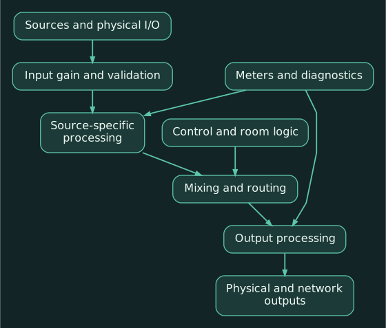
For a conferencing microphone, the more specific path is commonly:
- Analog or network input
- Input gain and signal validation
- Acoustic echo cancellation
- Microphone EQ or filtering
- Noise reduction or AGC
- Automixing
- Routing and mix-minus
- Far-end send, recording or reinforcement buses
Exact ordering varies by platform. Q-SYS recommends placing microphone processing after its AEC component because the canceller performs best when the microphone and reference paths remain predictable. (help.qsys.com) Shure devices may integrate AEC, noise reduction, AGC and automixing inside the microphone or processor. Preserve the manufacturer’s intended internal order rather than recreating the same processing a second time.
2. Organize the file by function
A practical DSP file could use pages, partitions or schematic sections like these:
| Section | Purpose |
|---|---|
00_PROJECT | Project name, revision, author, sample rate and notes |
10_IO_MAP | Physical, Dante, AES67, USB and codec connections |
20_MIC_INPUTS | Microphone gain, AEC and channel processing |
30_PROGRAM_INPUTS | HDMI, Bluetooth, playback and auxiliary sources |
40_MIXING | Automixers, matrices and functional buses |
50_ROOM_MODES | Combining, partition and operating-state logic |
60_OUTPUTS | Zone EQ, delay, limiter and physical outputs |
70_CONFERENCE | USB, VoIP, soft-codec and mix-minus paths |
80_CONTROL_LOGIC | User controls, presets, GPIO and state logic |
90_SERVICE | Meters, test generators and diagnostic controls |
Q-SYS, Biamp Tesira and other platforms implement pages differently. The numbering principle remains useful because it keeps sections in a predictable order.
The cover section should record:
- Project and room names
- DSP model
- Software and firmware versions
- Sample rate
- Drawing revision
- Programmer
- Commissioning date
- Known limitations
- Default operating mode
- Location of configuration backups
3. Build repeatable input channel strips
Every similar microphone should pass through the same basic channel structure.
A microphone input strip might contain:
- Physical or Dante input
- Descriptive channel name
- Phantom-power and sensitivity setting
- Input meter
- AEC channel
- High-pass filter
- Parametric EQ
- Gain or trim
- Mute
- Automixer input
- Post-processing meter
Place equivalent blocks in the same order. If Mic 1 uses a high-pass filter before its EQ and Mic 2 uses the same blocks in reverse order for no documented reason, future service becomes needlessly suspicious.
Name the function and location
Use names such as:
MIC_RMA_CEILING_NORTHMIC_RMA_LECTERNSRC_RMB_HDMI_AUDIOBUS_COMBINED_AUTOMIXREF_RMA_AECOUT_RMA_CEILING_SPKSEND_USB_NEAR_END
Avoid:
Input 4Gain 17Mixer NewFinal Final Mixer 2
Channel names should follow the signal across Dante Controller, the DSP file, drawings and commissioning records whenever character limits allow.
4. Create buses based on purpose
A bus is a shared signal path serving a defined function.
Useful bus names include:
- Room speech
- Program audio
- Far-end send
- Far-end receive
- AEC reference
- Recording
- Assistive listening
- Lobby or overflow
- Voice lift
- Paging
Speech and program audio often require different processing. Speech may use automixing and high-pass filtering. Program audio may preserve stereo and wider frequency response.
Combining everything immediately into one MAIN MIX destroys flexibility. Keep the functional buses separate until the design actually requires them to meet.
Mix-minus
A conferencing destination generally receives the appropriate local sources while excluding its own return signal.
For a USB codec:
- USB receive goes to the room loudspeakers.
- Local microphone mix goes to USB transmit.
- USB receive must not be routed directly back to USB transmit.
That exclusion is called mix-minus: the destination receives the complete relevant mix minus itself.
Lesson 11: Mix-Minus examines these routes in detail. The file architecture should expose the send and return paths clearly.
5. Build the AEC reference intentionally
AEC needs a reference copy of audio that can emerge from the room loudspeakers and return through the microphones.
In a typical room without local voice lift, the reference should include:
- Far-end receive audio
- Program material played through the room
- Other electronic sources reproduced by the loudspeakers
It should exclude the local microphone being processed. Q-SYS specifically warns against feeding a microphone into its own reference or the reference of another microphone capturing the same talkers. (help.qsys.com)
A useful reference tap is commonly located:
- After user source-level controls
- After the source mix
- Before loudspeaker-specific EQ, delay and limiting
The AEC then sees the content and level actually requested for playback without treating speaker voicing as source content.
Avoid duplicate AEC. If an MXA microphone performs AEC, disable the equivalent processing in the downstream DSP unless the manufacturer explicitly documents another arrangement. Shure warns that cascading independent AEC stages can degrade performance. (shure.com)
6. Keep loudspeaker processing at the output
Each loudspeaker zone should have an identifiable output chain:
- Zone source or room bus
- User volume range
- System mute
- Zone EQ
- Delay
- High-pass and low-pass filters
- Limiter
- Output meter
- Analog, Dante or amplifier output
Speaker voicing belongs near the output because it describes the loudspeaker and acoustic zone.
A microphone EQ follows the microphone wherever it is routed. A ceiling-speaker EQ stays with that ceiling-speaker output regardless of which source is selected.
Protect fixed commissioning parameters from routine user control. A touchpanel volume command should operate a defined user-level block, not the same gain block used to calibrate amplifier sensitivity.
7. Separate audio from control and logic
Audio lines carry sound. Control lines change parameters. Logic lines represent states such as:
- Occupied or unoccupied
- Partition open or closed
- System on or off
- Call active
- Microphone active
- Emergency mute
- Preset selected
Keep the logic on its own page or area. The audio drawing should show where control acts, but it should not be buried under dozens of Boolean lines.
For each important state, establish one owner. If a room-combine state can be changed independently by the partition sensor, touchpanel, control processor and DSP snapshot, contradictory commands become likely.
Use a simple state hierarchy:
- Life-safety or emergency override
- Physical partition state
- Authorized operator mode
- Normal user controls
- Default startup state
8. Put meters at boundaries
Meters are most useful where responsibility changes.
Recommended test points include:
- Raw input
- Post-AEC microphone
- Automixer output
- Far-end send
- Far-end receive
- AEC reference
- Program bus
- Room bus
- Speaker output
- Recording or assistive-listening feed
A service technician should be able to follow a failed signal through those boundaries.
For example:
- Input meter active, post-AEC dead: conferencing-processing problem.
- Automixer active, USB send dead: routing or mix-minus problem.
- Room bus active, speaker output dead: output processing, mute or physical-output problem.
- Far-end receive active, AEC reference dead: incorrect reference routing.
Biamp’s signal-line tools similarly support tracing paths through matrices and finding mutes or broken AEC-reference routes. (support.biamp.com)
9. Practical example: standard conference room
Consider:
- Shure MXA ceiling microphone
- Q-SYS or Biamp DSP
- USB conferencing computer
- HDMI program audio
- Ceiling loudspeakers
The DSP architecture should expose four paths:
Near-end send
MXA → AEC → microphone processing → automix → USB transmit
Far-end receive
USB receive → room source mixer → speaker processing → amplifier
Program audio
HDMI audio → program gain → room source mixer → speakers
AEC reference
USB receive + HDMI program → AEC reference
The reference follows sources heard through the speakers. The local microphone mix does not loop back into it.
10. Practical example: two rooms with an airwall
Consider a divisible-room system:
- Two microphones assigned to Room A
- Two microphones assigned to Room B
- Two microphones near the airwall
Separate mode
- Room A microphones feed Room A’s AEC, automixer and outputs.
- Room B microphones feed Room B’s independent path.
- Airwall microphones remain muted.
- Each room uses its own far-end receive and AEC reference.
Combined mode
- All six microphones participate in the combined speech mix.
- Program and far-end sources route according to the combined-room operating plan.
- AEC channels receive the reference representing the combined loudspeaker feed.
- A single combined-room master controls the appropriate outputs.
Implement this as a documented room-mode state rather than twenty unrelated crosspoints operated independently.
Useful states:
MODE_SEPARATEMODE_COMBINEDMODE_TRANSITIONMODE_FAULT
The transition state can mute affected buses briefly while routes and references change. That prevents partial switching, feedback bursts and the classic “Room A is somehow hearing Room B’s Zoom call” experience.
Practical exercise
Sketch one existing conference room using only these named blocks:
- Microphone input
- AEC
- Automixer
- Far-end send
- Far-end receive
- Program input
- AEC-reference mixer
- Room-source mixer
- Speaker processing
- Amplifier output
Then mark the meter points where you would prove:
- The microphone entered
- AEC produced output
- The near-end mix reached the codec
- Far-end audio returned
- The AEC received its reference
- The speaker output remained active
Compact glossary
- Bus: Shared signal path serving a defined function.
- Matrix mixer: Routing structure connecting multiple inputs and outputs.
- Mix-minus: A destination mix excluding that destination’s own return.
- AEC reference: Copy of content expected to emerge from room loudspeakers.
- Automixer: Processor controlling multiple microphone contributions.
- Partition: DSP section or physical room divider, depending on context.
- State: Defined operating condition such as combined or separate.
- Test point: Meter or monitoring location at a functional boundary.
- Voice lift: Local reinforcement intended to improve talker coverage.
- Snapshot/preset: Stored collection of parameter values.
Review questions
- Why should program and speech buses remain separate until they need to be combined?
- Where should loudspeaker voicing generally appear in a DSP file?
- What audio normally belongs in an AEC reference?
Answers
-
They require different processing and may serve different destinations. Early combination removes useful control and routing options.
-
Near the applicable output, after the room or zone mix and before the physical amplifier or network output.
-
Far-end and program audio that will be reproduced by the room loudspeakers, after relevant source-level controls. Local microphones generally do not belong in their own reference.