
Levels and gain structure 10 min read
Levels, Decibels and Gain Structure
Follow acoustic, analog and digital levels through an AV system, understand decibel references and establish clean gain structure.
- Distinguish acoustic, analog, digital and amplified audio levels.
- Interpret dB, dBu, dBV, dBFS and dB SPL.
- Explain mic, line and speaker level.
- Explain why balanced audio rejects interference.
- Establish practical gain structure through a DSP system.
Why an AV engineer should care
Every DSP design assumes that audio enters at a sensible level. If that assumption is wrong, AEC, automixing, EQ and speaker processing all start their jobs with damaged material.
A signal entering too quietly brings noise along when someone boosts it downstream. A signal entering too loudly clips at the converter, and no later DSP block can reconstruct the missing waveform. The meters may keep bouncing cheerfully while the system sounds terrible.
This lesson establishes the level system used throughout the audio course.
1. Follow the audio through its different forms
A microphone-to-loudspeaker system crosses several domains:
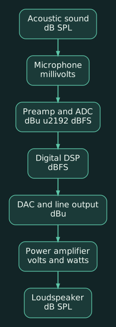
Each domain measures something different:
- Sound pressure reaches the microphone.
- The microphone converts pressure into a small electrical voltage.
- A preamplifier raises that voltage to a useful level.
- An analog-to-digital converter represents it numerically.
- The DSP processes those numbers.
- A digital-to-analog converter produces an analog line-level signal.
- The amplifier produces the voltage and current needed by the loudspeaker.
- The loudspeaker converts electrical power back into sound pressure.
The word “level” can therefore describe several unrelated quantities. Always ask: level measured where, and in what unit?
2. A decibel is a comparison
A plain dB describes a ratio between two values. It does not identify an absolute voltage, power or sound pressure unless a reference is attached.
For voltage:
dB = 20 log₁₀((V₂) / (V₁))
For power:
dB = 10 log₁₀((P₂) / (P₁))
Useful approximations:
| Change | Practical meaning |
|---|---|
| +3 dB power | Approximately twice the power |
| +6 dB voltage | Approximately twice the voltage |
| −6 dB voltage | Approximately half the voltage |
| +10 dB SPL | Often perceived as roughly twice as loud |
The last line is a psychoacoustic approximation. Perceived loudness also depends on frequency, program material, duration and the listener.
A gain block set to +6 dB means its output is 6 dB higher than its input. It does not tell us the resulting absolute level.
3. The references attached to dB
dBu
dBu measures analog voltage relative to 0.775 volts RMS.
0 dBu= 0.775 V RMS+4 dBu≈ 1.228 V RMS
+4 dBu is the traditional nominal professional line level. “Nominal” means a normal operating point, not the maximum the device can produce.
dBV
dBV measures voltage relative to 1 volt RMS.
0 dBV= 1 V RMS−10 dBV≈ 0.316 V RMS
−10 dBV is commonly associated with consumer and semi-professional equipment.
Because the references differ, +4 dBu and +4 dBV are not the same voltage. Biamp’s reference material confirms the common nominal values of +4 dBu = 1.228 V RMS and −10 dBV = 0.316 V RMS. (support.biamp.com)
dBFS
dBFS means decibels relative to digital full scale.
At an ADC, DAC or fixed digital interface:
0 dBFSis the maximum representable level.−20 dBFSis 20 dB below that maximum.- A conventional digital meter counts upward toward zero.
Some floating-point DSP engines can temporarily represent signals above nominal digital full scale internally. The converter boundary still has a maximum. If the signal reaches the DAC too hot, it clips unless it is attenuated first.
dB SPL
dB SPL measures acoustic sound pressure, referenced to 20 micropascals. It describes what happens in the air.
A DSP meter reading −20 dBFS cannot be converted directly into room SPL without knowing the output calibration, amplifier gain, loudspeaker sensitivity, distance and room behavior.
4. Mic, line and speaker level
These are operating ranges rather than exact universal voltages.
Microphone level
A microphone commonly produces millivolts. Its output changes with:
- Microphone sensitivity
- Talker level
- Distance
- Polar pattern
- Frequency
- Phantom powering and loading
A mic preamp may add 20–60 dB of gain before conversion.
Line level
Line level connects powered electronic devices such as:
- Wireless receiver to DSP
- DSP to amplifier
- Mixer to recorder
- Codec output to DSP input
Professional equipment commonly uses balanced +4 dBu nominal signals. Consumer devices often use unbalanced −10 dBV, although many current products offer configurable levels.
Speaker level
Speaker level appears after the power amplifier. It carries substantially more voltage and current than line level.
Never connect an amplifier’s speaker output directly to a normal DSP line input. A proper attenuator, transformer interface or purpose-built high-level input is required.
Phantom power
Phantom power commonly supplies 48 V DC to condenser microphones and active direct boxes over a balanced microphone connection. It does not make the audio “48 volts.” The DC supply and the differential audio occupy the same conductors in different ways.
Enable phantom power only where the connected device requires and supports it.
5. How balanced audio rejects noise
A balanced connection normally uses:
- Two signal conductors
- A shield
- A differential receiving circuit
In a common balanced-output design, the two conductors carry opposing versions of the wanted signal. Other balanced outputs drive only one conductor; matched impedances to ground, rather than opposite signal voltages alone, provide the balance needed for noise rejection. Interference induced into the cable tends to appear similarly on both conductors. The differential input responds to the difference between them, rejecting much of the shared interference.
This is called common-mode rejection. Shure describes the same mechanism: the balanced input responds to the difference between conductors while rejecting noise appearing equally on both. (content-files.shure.com)
A few useful cautions:
- Balanced does not mean stereo.
- An XLR connector does not guarantee a balanced circuit.
- A TRS connector may carry balanced mono, unbalanced stereo or another wiring scheme.
- The shield is not intended to carry either half of the audio signal.
- Poor termination can convert a balanced interface into a noisy unbalanced one.
Balanced wiring becomes especially valuable around power supplies, LED processors, amplifiers, motors and long equipment-room cable paths.
6. Gain structure: strong enough, with room left over
Good gain structure gives each device a healthy signal while preserving headroom for peaks.
Two failure modes define the boundaries:
Too little level
If the source or preamp is too low, later gain raises both the wanted audio and the accumulated noise.
Example:
- Wireless receiver output is set very low.
- DSP input gain remains near zero.
- A downstream mixer adds 25 dB.
- Speech becomes audible, along with hiss.
The signal was already weak when it entered the DSP.
Too much level
If the preamp or source output is too high, the ADC clips. Lowering a downstream fader makes the distortion quieter without removing it.
That distinction matters: a red input meter cannot be repaired with an output fader.
A practical commissioning sequence
-
Configure the source correctly.
Select mic or line output as appropriate. Use realistic program material or a normal talker. -
Select the DSP input type.
Choose mic, line or the manufacturer’s stated sensitivity range. Enable phantom power only when required. -
Set analog preamp gain.
Watch the meter immediately after the input converter. Adjust for a healthy nominal level with space for peaks. -
Keep ordinary DSP stages near unity.
Avoid scattering compensating+12 dBand−12 dBblocks throughout the file. -
Check every summing point.
Several individually safe channels can overload a mix bus when combined. -
Set the output conversion and amplifier sensitivity.
Protect the loudspeaker, then calibrate room SPL. -
Test quiet and loud users.
“Normal speech” from the commissioning engineer is only one operating condition.
Q-SYS currently recommends approximately −20 dBFS nominal at its analog inputs as a practical starting point. That target is specific to its gain structure and metering. (support.qsys.com) Other platforms and processing stages use different targets. Shure, for example, publishes different AGC target values for specific products. (shure.com) Record the target and meter location instead of copying one number into every design.
7. Practical example: wireless microphone into a room DSP
Suppose a Shure wireless receiver feeds a Q-SYS or Biamp analog input.
A sensible process is:
- Configure the receiver for line-level output.
- Configure the DSP input for the expected line-level range.
- Have the presenter speak at an actual presentation level.
- Adjust the receiver and input sensitivity so normal speech reaches the platform’s nominal target.
- Verify that louder speech leaves safe headroom.
- Keep the channel near unity through routing and mixing.
If the receiver is configured for mic output while the DSP expects line level, the signal may be needlessly weak. If the receiver delivers line level into a sensitive mic input, the input may clip before the DSP meter point you are staring at.
Document both settings.
8. Practical example: laptop playback into a conferencing DSP
A laptop headphone output may feed an unbalanced interface nominally closer to consumer level. Connecting it directly to a professional balanced input can produce:
- Low level
- Ground noise
- Incorrect stereo summing
- Different results among laptop models
- User volume controls that alter commissioning
A better design may use:
- A USB audio interface
- A balanced presentation interface
- A transformer-isolated stereo-to-mono interface
- USB audio directly into the DSP
The signal-flow drawing should identify the source format, nominal level, balanced or unbalanced connection and the intended input sensitivity. “Audio from laptop” is insufficient engineering information.
Practical exercise
Choose one existing room and trace one microphone channel from source to loudspeaker.
Record:
- Source output setting
- Balanced or unbalanced connection
- DSP input type and phantom-power state
- Preamp gain
- Normal speech level at the input meter
- Loud speech peak level
- Gain added or removed before the mixer
- Mix-bus peak
- DSP output level
- Amplifier input-sensitivity setting
Flag any location where more than about 10 dB is added merely to undo attenuation somewhere else. It may be legitimate, but it deserves an explanation.
Compact glossary
- ADC: Analog-to-digital converter.
- DAC: Digital-to-analog converter.
- dBu: Voltage level referenced to 0.775 V RMS.
- dBV: Voltage level referenced to 1 V RMS.
- dBFS: Digital level referenced to full scale.
- dB SPL: Acoustic sound-pressure level.
- Headroom: Space between normal operating level and clipping.
- Unity gain: Output level equals input level.
- CMRR: Common-mode rejection ratio.
- RMS: A voltage measurement representing effective signal energy.
- Clipping: Distortion caused by exceeding a stage’s maximum level.
Review questions
- Why can’t lowering the output fader repair an input that clipped at the ADC?
- What is the difference between
+4 dBuand−10 dBV? - Why does a balanced input reject interference?
Answers
-
The ADC already discarded part of the waveform. A later fader only reduces the level of the distorted signal.
-
They are analog voltage references.
+4 dBuis approximately 1.228 V RMS;−10 dBVis approximately 0.316 V RMS. -
The differential receiver responds to the voltage difference between its two conductors while rejecting noise appearing similarly on both.